How do you create a logic gate from truth table?
Creating a logic gate from a truth table involves determining the logical expression that represents the output based on the given inputs. The truth table outlines all possible combinations of inputs and their corresponding outputs. Here are step-by-step instructions on how to create a logic gate from a truth table:
Steps:
Understand the Truth Table:
- Review the truth table to understand the relationships between the inputs (usually labeled A, B, etc.) and the corresponding output (labeled Y). Each row in the table represents a unique combination of input values and the resulting output.
Identify the Logic Gate Type:
- Determine the type of logic gate you need to create based on the desired output for each input combination. Common logic gates include AND, OR, NOT, XOR, NAND, NOR, etc.
Write Boolean Expressions:
- Write Boolean expressions for each row of the truth table. Expressions describe the logic operation that produces the output for that specific combination of inputs. Use logic symbols such as AND (&), OR (|), NOT (~), etc.
Simplify Boolean Expressions:
- If possible, simplify the Boolean expressions using algebraic laws and theorems (e.g., Boolean algebra rules). Simplification helps reduce the complexity of the logic circuit.
Create a Logic Diagram:
- Based on the simplified Boolean expressions, create a logic diagram using standard symbols for the chosen logic gates. Each gate type has a specific symbol (e.g., ∧ for AND, ∨ for OR, ¬ for NOT).
Implement the Circuit:
- Implement the logic circuit using electronic components or a digital design tool. If you're working on a digital circuit, you can use electronic design automation (EDA) software to create the circuit diagram and simulate its behavior.
Example:
Let's consider a simple AND gate example:
| A | B | Y |
|---|---|---|
| 0 | 0 | 0 |
| 0 | 1 | 0 |
| 1 | 0 | 0 |
| 1 | 1 | 1 |
The Boolean expression for the AND gate is Y = A & B.
The logic diagram would have an AND gate symbol with inputs A and B and an output Y.
Remember, this process can be applied to other types of logic gates with different logical operations. The key is to analyze the truth table, express the logic using Boolean algebra, and represent it visually in a logic diagram.
Understanding the relationship between logic gates and truth tables
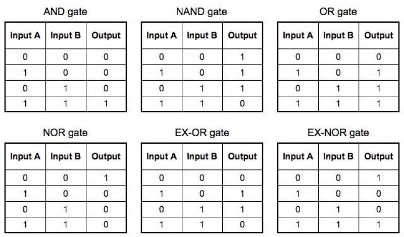
Logic gates are fundamental building blocks in digital circuits, performing basic logical operations like AND, OR, NOT, and NAND. Truth tables, on the other hand, are tabular representations of the output of a logic gate for every possible combination of inputs.
The relationship between logic gates and truth tables is direct and essential. Each logic gate has a corresponding truth table that defines its behavior for all possible input combinations. For instance, the AND gate's truth table shows that its output is 1 only when both inputs are 1.
Using truth tables, we can analyze the behavior of logic gates and predict their output for any given input combination. This relationship is crucial in designing and understanding complex digital circuits.
Converting a truth table into a Boolean expression
A Boolean expression is a combination of logical operators (AND, OR, NOT) and variables (A, B, C, etc.) that represents a logical relationship. Converting a truth table into a Boolean expression involves identifying the patterns of 1's and 0's in the output column and constructing a corresponding expression using logical operators.
For example, consider a truth table with three inputs (A, B, C) and one output:
| A | B | C | Output |
|---|---|---|---|
| 0 | 0 | 0 | 0 |
| 0 | 0 | 1 | 0 |
| 0 | 1 | 0 | 0 |
| 0 | 1 | 1 | 1 |
| 1 | 0 | 0 | 0 |
| 1 | 0 | 1 | 0 |
| 1 | 1 | 0 | 1 |
| 1 | 1 | 1 | 1 |
The corresponding Boolean expression for this truth table is:
Output = (B * C) + (A * B * C)
This expression represents the logic that generates the output values shown in the truth table.
Constructing logic circuits from Boolean expressions
Logic circuits are physical implementations of logical operations using logic gates. By understanding the relationship between Boolean expressions and logic gates, we can construct logic circuits from Boolean expressions.
The process involves breaking down the Boolean expression into its individual terms and representing each term using its corresponding logic gate. For instance, the expression (A * B) + (C * D) can be implemented using two AND gates and one OR gate.
Constructing logic circuits from Boolean expressions allows us to physically realize the logical relationships defined by the expressions.
Simplifying logic circuits for efficient implementation
Logic circuits can sometimes contain redundant or unnecessary elements that increase the circuit's complexity and cost of implementation. Simplifying logic circuits aims to reduce the number of gates and minimize interconnections while preserving the desired logical function.
Techniques like Boolean algebra, Karnaugh maps, and algebraic manipulation can be used to simplify logic circuits. These techniques help identify redundant terms, optimize gate placements, and reduce the overall complexity of the circuit.
Simplifying logic circuits not only improves their efficiency but also enhances their performance and reduces power consumption.
Applying logic gates to solve real-world problems
Logic gates and their applications extend far beyond digital circuits. They play a crucial role in various fields, including:
Computer science: Logic gates form the foundation of digital computers, enabling them to perform computations, make decisions, and process information.
Engineering: Logic gates are employed in control systems, communication networks, and electronic devices to regulate signal flow, perform operations, and implement specific functionalities.
Mathematics: Logic gates are used to represent and manipulate logical relationships, providing a powerful tool for solving problems in logic, set theory, and discrete mathematics.
Artificial intelligence: Logic gates are fundamental components in artificial intelligence systems, enabling them to process information, make inferences, and perform complex decision-making tasks.
In conclusion, logic gates and truth tables are fundamental concepts in digital electronics and have wide-ranging applications in various fields. Understanding their relationship and mastering their use is essential for designing efficient and sophisticated digital systems and solving real-world problems.