How to calculate gear displacement?
Calculating gear displacement is an important aspect of mechanical engineering, especially in applications where precise motion control and positioning are required. Gear displacement, often referred to as linear displacement or linear travel, represents the distance that an object, such as a rack or linear actuator, moves in response to the rotational motion of a gear or gear system. To calculate gear displacement, you need to consider the gear's parameters and the specific gear arrangement. Here's how to do it:
1. Understand Gear Terminology:
Before calculating gear displacement, it's important to be familiar with the following gear terminology:
Pitch Circle: The circle through which the teeth of a gear are geometrically defined. It's also called the pitch circle diameter (PCD).
Pitch Diameter (D): The diameter of the pitch circle. It's equal to the number of teeth (N) divided by the diametral pitch (P).
Diametral Pitch (P): A measure of the size of the gear teeth. It represents the number of teeth per inch of the pitch diameter. The formula to calculate P is P = N / D.
Module (M): A metric measure of gear tooth size, defined as the pitch diameter (D) divided by the number of teeth (N). M = D / N.
2. Determine Gear Ratios:
In a gear system, the displacement of one gear is transmitted to another gear through the meshing of their teeth. The gear ratio (GR) is defined as the ratio of the number of teeth on the driven gear (output gear) to the number of teeth on the driving gear (input gear). Gear displacement depends on this ratio.
3. Calculate Linear Displacement:
To calculate the linear displacement (Dlinear) produced by a rotating gear, use the following formula:
Dlinear = (Θ * D) / (2 * π * GR)
- Dlinear: Linear displacement (in units of length, e.g., millimeters or inches).
- Θ (Theta): The angular displacement of the input gear (in radians). This is the angle through which the input gear has rotated.
- D: Pitch diameter of the driven gear (in units of length).
- π (Pi): A mathematical constant approximately equal to 3.14159.
- GR: Gear ratio (output teeth/input teeth).
Make sure to use consistent units for all variables in the formula.
4. Solve for Linear Displacement:
Plug in the values for Θ (in radians), D (pitch diameter of the driven gear), and the gear ratio (GR) into the formula to calculate the linear displacement.
Example:
Let's say you have an input gear with 20 teeth (N1), a driven gear with 80 teeth (N2), and an angular displacement of 30 degrees (Θ). The pitch diameter of the driven gear (D) is 50 mm. Calculate the linear displacement.
First, calculate the gear ratio (GR):
GR = N2 / N1 = 80 / 20 = 4
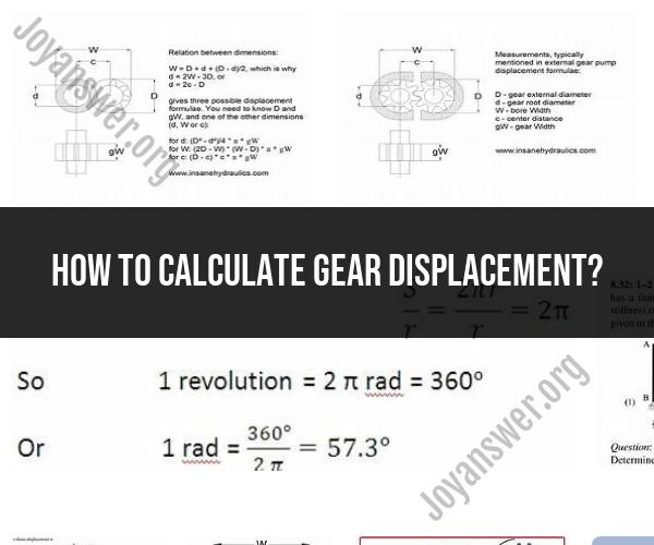
Convert the angular displacement from degrees to radians:
Θ = (30 degrees) * (π radians / 180 degrees) ≈ 0.5236 radians
Now, use the formula to calculate linear displacement:
Dlinear = (0.5236 radians * 50 mm) / (2 * π * 4) ≈ 2.083 mm
So, the linear displacement produced by the gear system is approximately 2.083 millimeters.
Understanding Gear Displacement Calculation
Gear displacement is the volume of fluid that is displaced by a gear pump in one revolution. It is an important parameter to consider when designing and sizing gear pumps, as it determines the flow rate of the pump.
Gear displacement is calculated using the following formula:
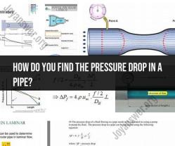
Gear displacement = (gear width * gear height * gear pitch diameter * π) / 2
where:
- Gear width is the width of the gear in the direction of rotation.
- Gear height is the height of the gear in the direction perpendicular to rotation.
- Gear pitch diameter is the diameter of a circle that passes through the centers of the gear teeth.
- π is a mathematical constant equal to approximately 3.14.
Gear Displacement Formula and Its Practical Uses
The gear displacement formula can be used to calculate the flow rate of a gear pump using the following equation:
Flow rate = (gear displacement * pump speed) / 60
where:
- Flow rate is the volume of fluid that is pumped in one minute.
- Gear displacement is calculated using the formula above.
- Pump speed is the number of revolutions per minute that the pump is rotating.
The gear displacement formula can also be used to calculate the required size of a gear pump for a given application. For example, if you know the desired flow rate and pump speed, you can use the formula to calculate the required gear displacement.
How to Calculate Gear Displacement in Mechanical Systems
To calculate gear displacement in mechanical systems, you will need to measure the following dimensions:
- Gear width
- Gear height
- Gear pitch diameter
Once you have these measurements, you can use the gear displacement formula to calculate the displacement.
Here is an example of how to calculate gear displacement in a mechanical system:
Gear width = 1 inch
Gear height = 2 inches
Gear pitch diameter = 3 inches

Gear displacement = (1 inch * 2 inches * 3 inches * π) / 2
= 6π cubic inches
Once you have calculated the gear displacement, you can use it to calculate the flow rate of the gear pump or to determine the required size of a gear pump for a given application.
Practical Uses of Gear Displacement Calculation
Gear displacement calculation is used in a variety of industries, including:
- Automotive
- Industrial
- Hydraulic
- Pneumatic
- Aerospace
It is used to design and size gear pumps for a variety of applications, such as:
- Fuel pumps
- Oil pumps
- Power steering pumps
- Brake pumps
- Hydraulic pumps
- Pneumatic pumps
- Aircraft fuel pumps
Gear displacement calculation is an important tool for engineers and designers who work with gear pumps. It allows them to ensure that the pumps are properly sized and designed for the specific application.