What are isometric piping drawings?
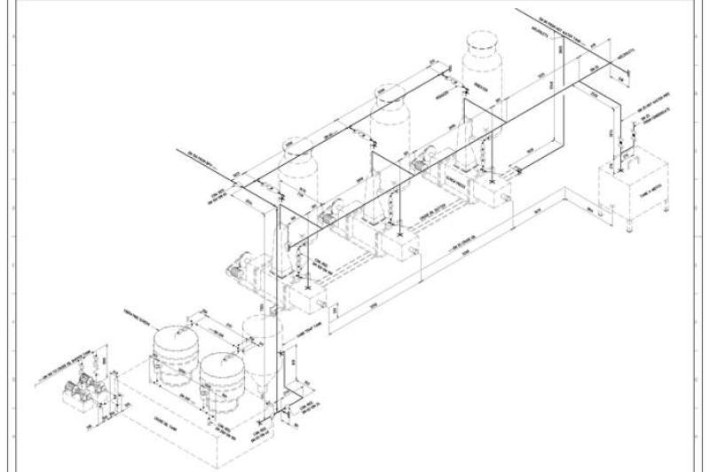
Isometric piping drawings are technical illustrations that represent the three-dimensional layout of piping systems in a 2D format. These drawings provide a clear and detailed view of how pipes, fittings, and other components are arranged in space. The term "isometric" refers to the equal measure of the three axes in a 3D space, and isometric drawings are a type of axonometric projection.
Key features of isometric piping drawings include:
3D Representation:
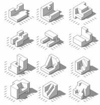
- Isometric piping drawings provide a 3D representation of a piping system, allowing viewers to see how pipes and components are oriented in three-dimensional space.
Equal Scale:
- Unlike perspective drawings where objects appear smaller as they recede into the distance, isometric drawings maintain an equal scale along each axis. This means that the size of objects remains consistent regardless of their distance from the viewer.
Angles:
- Isometric drawings are typically created with lines at 30-degree angles from the horizontal. This creates a balanced and visually consistent representation of the piping system.
Piping Components:
- The drawings include various piping components such as pipes, elbows, tees, valves, pumps, and other fittings. Each component is represented with accuracy in terms of its size, shape, and orientation.
Connectivity:
- Isometric piping drawings clearly show how different components are connected and how the piping system flows. This is crucial for understanding the layout and functionality of the system.
Annotations:
- Annotations, labels, and symbols are often added to isometric piping drawings to provide additional information. This can include pipe sizes, material specifications, flow directions, and other relevant details.
Scale Representation:
- While isometric drawings maintain an equal scale along each axis, it's important to note that the drawings may not represent the true size of components. Designers often use specific scales to fit the entire piping system onto a manageable drawing sheet.
Isometric piping drawings are widely used in engineering, architecture, and construction to communicate the design and layout of piping systems. They offer a comprehensive view that helps designers, engineers, and other stakeholders visualize the spatial relationships between components. These drawings are particularly valuable in industries where accuracy in system layout and functionality is crucial, such as in HVAC systems, industrial plants, and chemical processing facilities.
Computer-aided design (CAD) software is commonly used to create isometric piping drawings, allowing for efficient design, modification, and sharing of detailed piping system plans.
Sure, here is a breakdown of representing piping systems in isometric drawings:
Representing piping systems in isometric drawings: Understanding the conventions and techniques
Isometric drawings are a crucial tool for engineers and designers involved in piping systems. They provide a clear and concise representation of the three-dimensional layout of a piping system in a two-dimensional plane. Understanding the conventions and techniques used in isometric drawings is essential for effectively representing and interpreting piping systems.
Basic Principles of Isometric Drawings:
Isometric projection: Isometric drawings utilize isometric projection, where angles are preserved, and lengths are represented at a consistent scale.
Isometric grid: An isometric grid, composed of evenly spaced lines at 60-degree angles, forms the foundation of isometric drawings.
Piping symbols: Standardized symbols are employed to represent various piping components, such as pipes, valves, fittings, and flanges.
Conventions and Techniques:
Line weight: Thicker lines represent main piping, while thinner lines represent branch lines and instrumentation lines.
Arrowheads: Arrowheads indicate the direction of fluid flow within the piping system.
Centerlines: Centerlines are drawn along the center of pipes to represent their actual location in space.
Dimensioning: Dimensions are added to specify the lengths, diameters, and offsets of piping components.
Creating Isometric Piping Drawings:
Sketch the piping layout: Begin by sketching the piping layout onto an isometric grid paper or using CAD software.
Draw the piping lines: Represent pipes using lines parallel to the isometric grid lines.
Add piping symbols: Place appropriate symbols for valves, fittings, and flanges at the corresponding locations.
Label components: Label each piping component using its designated tag number or description.
Dimension the drawing: Add dimensions to specify the lengths, diameters, and offsets of piping components.
Interpreting and Understanding Isometric Piping Drawings:
Identify the isometric grid: Recognize the isometric grid lines and use them to orient the drawing correctly.
Trace the piping lines: Follow the piping lines to visualize the three-dimensional layout of the piping system.
Locate piping components: Identify and locate various piping components based on their symbols and labels.
Interpret dimensions: Understand the dimensions to determine the lengths, diameters, and offsets of piping components.
Analyze the piping system: Analyze the piping system for its functionality, safety, and adherence to design standards.
Isometric drawings play a vital role in piping system design, construction, and maintenance. By understanding the conventions and techniques used in isometric drawings, engineers and designers can effectively represent and interpret piping systems, ensuring the proper execution and operation of these critical components.
I hope this information is helpful. Please let me know if you have any other questions.