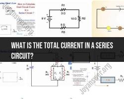
What is used to measure the current in Series circuits?
To measure current in a series circuit, an ammeter is used. An ammeter is a measuring instrument specifically designed to measure electric current in a circuit. Here are the steps to measure current in a series circuit using an ammeter:
Select the Ammeter:
- Choose an ammeter with an appropriate current range for the circuit you are working with. The ammeter's current range should be equal to or greater than the expected current in the circuit.
Turn Off the Circuit:
- Before connecting the ammeter, make sure the circuit is turned off. This is important to prevent damage to the ammeter and ensure safety during the measurement.
Insert the Ammeter in Series:
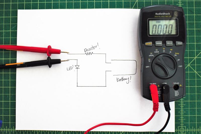
- For a series circuit, the ammeter is connected in series with the components through which you want to measure the current. Open the circuit at any point, and connect the ammeter in series by placing it in the path of the current flow.
Follow Polarity:
- Pay attention to the polarity of the ammeter. Connect the positive (red) lead of the ammeter to the higher potential side of the circuit, and the negative (black) lead to the lower potential side. This ensures that the current flows through the ammeter in the correct direction.
Close the Circuit:
- After connecting the ammeter, close the circuit by turning it on. The current will now flow through the ammeter, allowing it to measure the current passing through that specific point in the circuit.
Read the Ammeter:
- Once the circuit is closed, the ammeter will provide a reading indicating the amount of current flowing through the circuit. Read the value displayed on the ammeter's scale or digital display.
Record the Measurement:
- Record the current measurement for reference or analysis.
Turn Off the Circuit and Disconnect the Ammeter:
- After taking the measurement, turn off the circuit, and disconnect the ammeter. This ensures safety and prevents unnecessary power consumption.
Remember, connecting an ammeter in parallel to measure current in a series circuit is not appropriate because it can disrupt the normal current flow. Always connect the ammeter in series for accurate current measurements. If you're not familiar with electrical circuits or lack experience, consider seeking guidance from someone with expertise in electrical work to ensure safety and accurate measurements.
Which instruments are commonly used to measure current in series circuits?
The primary instrument used to measure current in a series circuit is an ammeter. It is connected in series with the circuit, meaning it is placed directly in the path of the current flow. When connected in this way, the entire current flowing through the circuit also flows through the ammeter, allowing it to accurately measure the current.
Here's a breakdown of the types of ammeters used in series circuits:
1. Analog Ammeters: These ammeters use a moving coil and a permanent magnet to deflect a needle across a calibrated scale. The deflection of the needle is proportional to the current flowing through the ammeter.
2. Digital Ammeters: These ammeters use electronic components to convert the current flowing through the circuit into a digital reading displayed on a screen. They offer greater accuracy and precision than analog ammeters.
3. Clamp Meters: These ammeters can measure current without making direct contact with the circuit. They use a clamp that surrounds the conductor carrying the current to measure the electromagnetic field generated by the current. This makes them ideal for measuring current in high-voltage or hard-to-reach circuits.
In addition to ammeters, other instruments can be used to indirectly measure current in series circuits:
1. Voltmeters: While voltmeters primarily measure voltage, they can be used in conjunction with Ohm's Law (V = I * R) to calculate current. By measuring the voltage across a known resistance in the circuit, the current can be calculated.
2. Multimeters: These versatile instruments can measure voltage, current, and resistance. They are often used in electrical troubleshooting and testing.
Choosing the appropriate instrument for measuring current depends on several factors:
- Accuracy and precision requirements: High-precision applications may require digital ammeters.
- Current range: Ensure the chosen instrument can measure the expected current range in the circuit.
- Safety considerations: High-voltage circuits require ammeters with proper safety features.
- Convenience and portability: Clamp meters and multimeters offer portability and convenience.
It's important to ensure the chosen instrument is compatible with the type of circuit and meets the specific needs of the application.


